

How Does the Electric Double Depamu-pumps.com/Diaphragm-Pump.html target='_blank'>Diaphragm Pump Work?
Introduction
The electric double diaphragm pump, also known as an Electric Operated Double Diaphragm (EODD) pump, represents one of the most significant advancements in industrial fluid handling technology in recent decades. While air-operated double diaphragm (AODD) pumps have dominated the market for decades due to their robustness and versatility, the emergence of electrically driven alternatives has introduced a new paradigm of energy efficiency, precision control, and operational simplicity. Understanding how these pumps work requires a careful examination of their mechanical design, the sequence of operations during each pumping cycle, and the key components that enable their unique functionality.
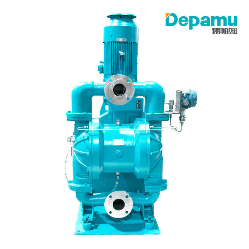
Fundamental Principle: Positive Displacement
At its core, the electric double diaphragm pump is a positive displacement pump. Unlike centrifugal pumps that rely on rotating impellers to impart velocity to fluids, positive displacement pumps work by trapping a fixed volume of fluid and then forcing it into the discharge system. The electric double diaphragm pump achieves this through the reciprocating motion of two flexible diaphragms, which are typically made from materials such as PTFE, Santoprene, or rubber compounds selected for compatibility with the pumped medium.
The fundamental operating principle is elegantly simple: an electric motor drives a mechanism that causes two diaphragms to move back and forth in a coordinated, alternating fashion. As one diaphragm moves outward, it creates a vacuum that draws fluid into its chamber. Simultaneously, the other diaphragm moves inward, pressurizing its chamber and forcing fluid out through the discharge port. This alternating action produces a continuous, though slightly pulsating, flow of fluid through the pump.
The Drive Mechanism: Converting Rotary Motion to Linear Reciprocation
The distinguishing feature of an electric double diaphragm pump compared to its air-operated counterpart is, of course, its power source. An electric motor serves as the prime mover, and the critical engineering challenge lies in converting the motor's rotary motion into the linear reciprocating motion required to drive the diaphragms.
Several mechanical configurations are employed to achieve this conversion. One common approach involves a camshaft mechanism. The electric motor rotates a camshaft, and a cam follower mounted on a yoke or connecting rod translates the rotational movement into linear displacement. The cam profile is designed to provide the appropriate stroke length and velocity profile for optimal pumping performance.
Another widely used mechanism is the eccentric shaft or crankshaft system. Here, the motor rotates an eccentric shaft, and a connecting rod converts this rotation into the back-and-forth motion of a piston or thrust rod. This thrust rod is mechanically linked to the diaphragms, either directly or through a coupling member. In some designs, a slider-crank mechanism is employed, similar in principle to the mechanism used in internal combustion engines.
More advanced designs incorporate a linear actuator driven by a servo motor. In these systems, the servo motor provides precise control over the position, velocity, and acceleration of the diaphragm movement, enabling highly accurate flow control and the ability to program specific pumping profiles.
Regardless of the specific mechanism employed, the fundamental requirement is the same: convert the continuous rotary motion of the electric motor into a controlled, reciprocating linear motion that drives the two diaphragms in opposition to each other.
The Diaphragm Assembly and Central Shaft
The two diaphragms are the heart of the pump. They are typically circular, flexible membranes that are clamped at their periphery between the pump housing components. The center of each diaphragm is mechanically connected to a common shaft or connecting rod. This central shaft ensures that the two diaphragms move in unison: when one diaphragm moves inward (toward the center of the pump), the other must move outward, and vice versa.
This mechanical coupling is fundamental to the pump's operation. The shaft transmits force from the drive mechanism to the diaphragms and ensures the synchronized, alternating motion that produces continuous flow. In electric double diaphragm pumps, the space between the two diaphragms—the region surrounding the central shaft—is typically filled with a hydraulic fluid, such as oil. This fluid serves multiple purposes: it lubricates the moving parts, it helps to balance the forces on the diaphragms, and it provides a medium through which pressure can be transmitted if one diaphragm fails, preventing the pumped fluid from reaching the drive mechanism.
The Pumping Chambers and Check Valves
Each diaphragm separates the pump into two distinct regions: the air or drive chamber on one side (where the driving mechanism acts) and the fluid or pumping chamber on the other side (where the pumped medium is contained). The pumping chamber is the working volume that expands and contracts with the diaphragm's movement.
Fluid enters and exits each pumping chamber through check valves. Each chamber is equipped with two check valves: an inlet (suction) valve and an outlet (discharge) valve. These are typically ball-type check valves, though other designs such as flap valves or poppet valves may also be used depending on the application and the nature of the pumped fluid.
The check valves are critical to the pump's function. They ensure unidirectional flow through the pump: fluid can only enter through the inlet valve and can only exit through the discharge valve. When the diaphragm moves outward, creating a vacuum in the chamber, the inlet check valve opens while the discharge valve remains closed, allowing fluid to be drawn into the chamber. When the diaphragm moves inward, pressurizing the chamber, the inlet valve closes and the discharge valve opens, allowing fluid to be expelled into the discharge manifold.
The Complete Pumping Cycle
To fully understand how an electric double diaphragm pump works, it is helpful to trace the complete pumping cycle through its individual phases.
Phase 1: Suction Stroke on Side A. The electric motor drives the mechanism such that Diaphragm A moves away from the center of the pump, expanding the volume of Pumping Chamber A. This expansion reduces the pressure within the chamber, creating a partial vacuum. The pressure differential across the inlet check valve causes it to open, and fluid from the suction line flows into Chamber A. During this same phase, the discharge check valve for Chamber A remains closed due to the pressure from the discharge manifold.
Phase 2: Discharge Stroke on Side B. Because the two diaphragms are mechanically linked by the central shaft, as Diaphragm A moves outward, Diaphragm B must move inward. This inward movement reduces the volume of Pumping Chamber B, pressurizing the fluid contained within it. The increased pressure forces the discharge check valve for Chamber B to open, allowing fluid to flow out into the discharge manifold. The inlet check valve for Chamber B remains closed due to the pressure within the chamber.
Phase 3: Reversal and Alternation. Once the diaphragms reach the end of their stroke, the drive mechanism reverses the direction of motion. Diaphragm A now moves inward while Diaphragm B moves outward. This reverses the roles of the two chambers: Chamber A, which was filling during the previous phase, now discharges its contents, while Chamber B, which was discharging, now draws in a fresh charge of fluid. This alternating cycle repeats continuously, producing a steady, though pulsating, flow of fluid through the pump.
The frequency of this cycle—the number of strokes per minute—determines the flow rate of the pump. In electric double diaphragm pumps, the stroke rate can be precisely controlled by adjusting the speed of the electric motor, often through a variable frequency drive (VFD) or variable speed drive. This provides a level of flow control that is not achievable with simple on/off pneumatic pumps.
Self-Priming Capability
One of the most valuable characteristics of diaphragm pumps, including electric double diaphragm pumps, is their self-priming capability. Because the pump operates by creating a vacuum in the pumping chamber, it can draw fluid up from a source located below the pump, even when the suction line is initially filled with air. The check valves prevent the fluid from draining back out of the pump between strokes, allowing the pump to progressively evacuate the suction line and establish a prime.
This self-priming capability makes electric double diaphragm pumps particularly suitable for applications where the pump must be located above the fluid source, such as drawing chemicals from drums or tanks, or in sump and wastewater transfer applications.
Dry-Run Resistance
Closely related to self-priming is the pump's ability to run dry without damage. Because the diaphragms and check valves do not rely on the pumped fluid for lubrication or sealing, the pump can operate for extended periods with no fluid in the chambers. This is a significant advantage over many other pump types, such as centrifugal or rotary gear pumps, which can be severely damaged by dry running. In electric double diaphragm pumps, the diaphragms simply continue to flex without the hydraulic load of the fluid, and the pump resumes normal operation as soon as fluid becomes available.
Seal-less Design and Leak Prevention
A fundamental design feature of all diaphragm pumps is the absence of dynamic seals, such as mechanical seals or packing, that are common in other pump types. The pumped fluid is completely contained within the pumping chamber by the diaphragm itself, which acts as a static seal at its clamped periphery. This seal-less construction eliminates a primary source of leaks, making diaphragm pumps ideal for handling hazardous, toxic, or valuable fluids.
In electric double diaphragm pumps, this leak-free characteristic is particularly important because the drive mechanism—including the motor, gears, and bearings—is physically separated from the pumped fluid by the diaphragm and the intermediate fluid (if used). Even if a diaphragm were to rupture, the intermediate fluid would typically provide a secondary barrier, and leak detection systems can be integrated to alert operators to the failure before the pumped fluid reaches the drive end.
Comparison with Air-Operated Diaphragm Pumps
Understanding the electric double diaphragm pump is facilitated by comparing it with the more established air-operated double diaphragm (AODD) pump. While both types share the fundamental double-diaphragm, positive-displacement design, they differ in several key respects.
The most obvious difference is the power source. AODD pumps use compressed air as the driving force, while EODD pumps use an electric motor. This fundamental difference has cascading implications for performance and operating characteristics.
In terms of energy efficiency, Electric Diaphragm Pumps have a significant advantage. Compressed air is a relatively expensive form of energy; generating it typically involves compressing atmospheric air, which is inherently inefficient due to heat losses and the energy required to overcome the pressure differential. Studies indicate that electric diaphragm pumps can reduce energy consumption by a factor of five or more compared to equivalent AODD pumps. For continuous-duty applications, this energy savings can be substantial and often justifies the higher initial cost of an EODD pump within a relatively short payback period.
Flow control is another area where electric diaphragm pumps excel. In an AODD pump, the flow rate is controlled by adjusting the air pressure and volume supplied to the pump. This method of control is somewhat crude and can result in imprecise flow rates. In contrast, an EODD pump can be controlled by varying the speed of the electric motor, typically through a VFD. This provides smooth, precise, and repeatable control over the flow rate, making EODD pumps suitable for metering and dosing applications where accuracy is critical.
Noise is another consideration. AODD pumps are known for the characteristic "chattering" sound produced by the rapid switching of their air valves. Electric diaphragm pumps are significantly quieter in operation, which is advantageous in environments where noise is a concern.
However, AODD pumps retain certain advantages. They are inherently safe in explosive or flammable atmospheres because they produce no electrical sparks, and they are simpler in construction, which can translate to lower maintenance costs in some applications. AODD pumps also have a wider tolerance for extreme operating conditions, such as very high or very low temperatures, and they can be easily stalled against back pressure without damage.
Applications of Electric Double Diaphragm Pumps
The unique combination of features offered by electric double diaphragm pumps—energy efficiency, precise flow control, self-priming capability, dry-run resistance, and seal-less construction—makes them suitable for a wide range of industrial applications.
In the chemical processing industry, EODD pumps are used for transferring acids, bases, solvents, and other aggressive chemicals. The availability of pump bodies in materials such as polypropylene, stainless steel, and aluminum, combined with diaphragms in PTFE and other chemically resistant elastomers, allows these pumps to handle a broad spectrum of corrosive media.
In water and wastewater treatment, electric diaphragm pumps are employed for dosing chemicals such as coagulants, flocculants, and disinfectants. The precise flow control capabilities of EODD pumps make them particularly well-suited for these applications, where accurate dosing is essential for process efficiency and regulatory compliance.
The food and beverage industry utilizes electric diaphragm pumps for transferring ingredients, product concentrates, and cleaning solutions. The seal-less design and the availability of FDA-compliant materials make these pumps hygienic and safe for food contact applications.
In the paint and coatings industry, EODD pumps handle pigments, resins, solvents, and finished paint products. Their ability to pump high-viscosity fluids without shearing or damaging the product is a significant advantage over other pump technologies.
Ceramic and mining operations use electric diaphragm pumps for transferring abrasive slurries containing high concentrations of solids. The rugged construction of these pumps and their ability to handle particulate-laden fluids make them suitable for demanding environments where other pump types would quickly fail.
Conclusion
The electric double diaphragm pump represents a sophisticated marriage of simple mechanical principles and modern electric drive technology. By converting the rotary motion of an electric motor into the reciprocating motion of two coupled diaphragms, these pumps achieve efficient, reliable, and precisely controllable fluid transfer. The alternating suction and discharge cycles, governed by the coordinated action of the diaphragms and check valves, produce a continuous flow that can be adjusted to meet the specific requirements of each application.
The advantages of electric double diaphragm pumps—energy efficiency, precise flow control, self-priming, dry-run resistance, and leak-free operation—have established them as a compelling alternative to traditional air-operated diaphragm pumps in many industrial settings. As energy costs continue to rise and the demand for precise, sustainable fluid handling solutions grows, the electric double diaphragm pump is poised to play an increasingly prominent role in the industrial landscape. Understanding how these pumps work is essential for engineers, operators, and decision-makers seeking to optimize their fluid handling processes for efficiency, reliability, and environmental responsibility.