

The Comprehensive Guide to Depamu-pumps.com/Metering-pump.html target='_blank'>Metering Pump Selection
Introduction: The Precision Imperative
In the intricate world of industrial fluid handling, metering pumps stand as the custodians of process integrity. Unlike their centrifugal cousins that simply move fluid, metering pumps—also known as Dosing Pumps—are positive displacement devices engineered to deliver an exact, repeatable volume of liquid against varying system pressures . Their application spans from injecting precise chemical doses into municipal water supplies to metering critical catalysts in pharmaceutical synthesis. The selection of the correct metering pump is a decision of paramount importance; an undersized pump cannot meet process demands, while an oversized one sacrifices the very accuracy for which these pumps are specified . This article will systematically dissect the engineering considerations and systematic steps involved in sizing and selecting a metering pump, providing a framework for engineers and specifiers.
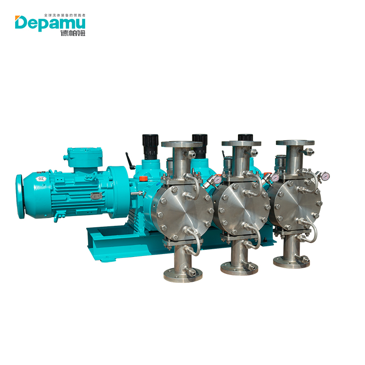
Part I: Defining the Hydraulic Operating Parameters
The foundation of any pump selection lies in defining the fundamental hydraulic requirements. However, for metering pumps, this stage carries a critical nuance: do not oversize.
1. Flow Rate and Turndown Ratio
The required flow rate is the starting point, typically expressed in gallons per hour (GPH) or liters per hour (LPH). A metering pump should ideally be sized so that the maximum expected operational flow rate falls between 85% and 90% of the pump's maximum rated capacity . This "sweet spot" ensures optimal accuracy and leaves a margin for unforeseen process increases.
Equally important is the turndown ratio—the pump's ability to maintain accuracy at reduced flow rates. The minimum operating capacity should generally not fall below 10% of the pump's full capacity . Pumps that need to operate in the 5% to 25% range are best served by designs that combine stroke length adjustment with variable speed drives, offering a wider effective turndown range .
2. Discharge Pressure and System Dynamics
The pump must be capable of overcoming the system's total discharge pressure, which includes static head, friction losses, and the pressure of the injection point. However, the relationship between pump pressure rating and application pressure is subtle. If the pump is rated for a pressure far exceeding the actual system backpressure, the inertia of the pumped fluid can prevent check valves from seating promptly, leading to overfeeding—a phenomenon where fluid continues to pass after the stroke is complete . To maintain hydraulic stability, the discharge pressure must exceed the suction pressure by at least 5 psi (0.35 bar) to prevent "flow through" . If the injection point is at a low pressure, a spring-loaded, diaphragm-type back-pressure valve is essential to artificially create the required hydraulic stability .
Part II: The Critical Role of Fluid Properties
While hydraulic parameters are the "what" of the selection process, the fluid properties are the "why." The chemical and physical nature of the pumped fluid dictates the mechanical architecture and materials of construction. As one industry guide emphasizes, "the basic properties of the fluid are of paramount importance in making the proper pump selection" .
1. Chemical Compatibility and Corrosion
The liquid end—the wetted parts of the pump—must withstand the chemical's corrosive, solvent, or erosive action . Standard pumps are suitable for water-like chemicals, but aggressive acids and caustics demand stainless steel, alloy (e.g., Hastelloy), or specialized plastics like PTFE/PFA . Solvent-based chemicals can dissolve plastic heads, while abrasive slurries require hardened materials or specific designs to mitigate erosion .
2. Viscosity and Rheology
Viscosity presents a challenge to the reciprocating action of the pump. Standard metering pumps handle viscosities up to ~1,500 cPs . As viscosity climbs, internal restrictions increase and the suction stroke struggles to fill the pumping chamber. For viscous fluids, engineers should specify designs that minimize internal flow restriction, such as:
-
Tubular or conical diaphragms that provide a straight-through flow path .
-
Over-sized check valves with spring assistance to ensure positive seating .
-
Slower stroking speeds to allow the chamber to fill completely .
Non-Newtonian fluids (which change viscosity under shear) add another layer of complexity. Thixotropic fluids (like molasses) thin out under shear, potentially allowing for successful pumping even if static viscosity appears too high. Conversely, dilatant fluids (like certain slurries) thicken under shear, often requiring testing to ensure pump suitability .
3. Vapor Pressure and NPSH
For any pump, the Net Positive Suction Head Available (NPSHA) must exceed the Net Positive Suction Head Required (NPSHR) to prevent cavitation. For metering pumps, the NPSHR is often driven by the acceleration head required to move the fluid into the chamber during the suction stroke .
The formula for NPSHA in a metering pump system is represented as:
NPSHA = P_A ± P_H - P_V - (Acceleration Head Loss) - (Friction Loss) .
For fluids with high vapor pressure (e.g., light hydrocarbons), the risk of cavitation is significant. Solutions include blanketing the supply tank with inert gas, increasing the suction head, or selecting a pump with a slower stroking rate . The fluid's temperature is also critical here, as vapor pressure rises and viscosity drops with increasing temperature.
4. Gas Release and Off-Gassing
Many chemicals, particularly oxidizers like sodium hypochlorite and hydrogen peroxide, release gas. In a reciprocating pump, this gas can accumulate in the liquid end, causing "vapor lock" and loss of prime . Peristaltic pumps are sometimes used for this reason. However, modern Diaphragm Pumps can handle off-gassing with specialized liquid ends designed for automatic venting or by utilizing flow meters that detect gas pockets and trigger an auto-degassing cycle .
Part III: Pump Architecture - Selecting the Technology
With process data defined, the engineer selects the appropriate pump technology. The decision typically rests on the balance of pressure, fluid containment, and maintenance.
1. Plunger/Piston Pumps
These pumps feature a reciprocating plunger in direct contact with the fluid, sealed by packing. They are the workhorses of high-pressure applications, capable of up to 5,000 psi .
-
Pros: High pressure capability, simple construction, high volumetric efficiency.
-
Cons: The packing seal is prone to wear and minor leakage. They are unsuitable for abrasive fluids (which damage the seal) and toxic or hazardous fluids .
2. Mechanically Actuated Diaphragm Pumps
A flexible diaphragm displaces the fluid, separating it from the mechanical drive.
-
Pros: Low cost, simple maintenance. Suitable for basic water treatment and chemical applications .
-
Cons: The diaphragm stroke is limited by mechanical linkage, generally resulting in lower pressure capabilities than hydraulic versions.
3. Hydraulically Actuated Diaphragm Pumps
This is the "gold standard" for demanding applications. A plunger pressurizes hydraulic fluid, which flexes a diaphragm. The PTFE or metallic diaphragm provides a complete, leak-free barrier .
-
Pros: No dynamic seals (leak-proof), high accuracy, handles high pressures and aggressive fluids .
-
Cons: Higher initial cost. However, they are the mandatory choice for toxic, hazardous, or zero-leak applications. Double-diaphragm heads with leak detection alarms are available for critical services .
4. Peristaltic Pumps
While not a traditional reciprocating metering pump, peristaltic pumps are often considered for dosing due to their accuracy and simplicity.
-
Pros: The fluid touches only the tubing (total containment). Excellent for abrasives, off-gassing, and viscous fluids. Can run dry .
-
Cons: Limited pressure capabilities (often <100 psi), pulsation (though less at high speed), and the need for periodic tube replacement .
Part IV: System Integration and Control
Selecting the pump is only half the battle. A properly designed system ensures the pump performs to its specification .
1. Drive Mechanisms and Environmental Factors
The drive mechanism must match available utilities and environmental conditions. Electric motors are standard, while pneumatic drives are used in explosive/hazardous areas. The pump's environment matters; direct sunlight, rain, or extreme temperatures can degrade performance. Pump enclosures must be specified with appropriate IP/NEMA ratings for the environment .
2. Piping Configuration
-
Suction Piping: Often one size larger than the pump connection to minimize acceleration head losses. Avoid hard piping smaller than 1/2 inch. A suction strainer is essential to protect the check valves from debris .
-
Discharge Piping: Must be sized for the discharge pressure. Isolation valves (preferably ball valves) should be installed for maintenance.
-
Calibration Column: A crucial accessory for verifying pump accuracy. A tall, thin cylinder on the suction side allows for a draw-down test, providing the most accurate verification of flow rate .
3. Safety and Auxiliary Components
-
Relief Valve: An external relief valve is recommended even if the pump has an internal one, set at 10% above the maximum operating pressure .
-
Pulsation Dampener: While not always essential for low-flow applications, a dampener minimizes pressure spikes and piping harmonics, extending the life of the system .
-
Injection Quills and Check Valves: Ensure proper dispersion at the injection point and prevent backflow .
4. Control Methods
The method of control determines how the pump interacts with the process. Manual micrometer dials adjust stroke length. For automation, a 4-20 mA analog signal or a digital pulse signal varies the stroke frequency proportionally to a process variable (like flow or pH) . The combination of stroke length and speed adjustment allows for fine-tuning and a wide turndown ratio.
Conclusion: A Systematic Approach to Selection
Selecting a metering pump is a systematic, multi-step engineering process. The decision matrix begins with the process data: flow, pressure, fluid chemistry, viscosity, and vapor pressure. It proceeds to choose the pump architecture that safely and effectively houses that fluid (typically leading to a hydraulic diaphragm for critical applications). Finally, it culminates in designing a support system—piping, valves, and controls—that enables the pump to operate at its peak accuracy.
The ultimate goal is not just to move a fluid, but to measure it. By respecting the "85-90% capacity" rule for sizing, rigorously evaluating fluid properties, and integrating the correct system components, engineers can ensure a long service life of precise, reliable operation. The final piece of the puzzle is choosing a reputable manufacturer with a proven track record and verifying that spare parts and technical support are accessible