

Depamu Corrosion Inhibitor Injection Skid Complete with Additional Standby Pump: A Comprehensive Engineering Solution for Asset Integrity
Abstract
Corrosion represents one of the most persistent and costly threats to capital-intensive assets across the oil and gas, petrochemical, power generation, and water treatment industries. The effectiveness of corrosion inhibitors, however, is entirely contingent upon the precision and reliability of the delivery system. A corrosion inhibitor that is under-dosed leaves metallic surfaces exposed to aggressive electrochemical attack, while an over-dosed chemical stream wastes expensive product and can contaminate downstream processes. The Depamu Corrosion Inhibitor Injection Skid—configured with a dedicated duty pump and an additional standby pump—addresses this challenge through a factory-built, modular solution that integrates storage, metering, control, and injection into a single pre-assembled unit. This article provides a comprehensive technical analysis of the Depamu skid, examining its mechanical architecture, the engineering rationale for duty/standby pump redundancy, operational mechanisms, international standards compliance, material selection criteria, control philosophy, and maintenance considerations.
1. Introduction: The Criticality of Precision Chemical Injection
Industrial process streams—whether crude oil, natural gas, boiler feedwater, or cooling water—are inherently corrosive. Dissolved oxygen, hydrogen sulfide (H₂S), carbon dioxide (CO₂), and various ionic species create electrochemical environments that rapidly degrade carbon steel and other common construction materials. Uncontrolled corrosion leads to pinhole leaks, catastrophic pipe ruptures, unplanned maintenance shutdowns, and product contamination. Corrosion inhibitors function by forming a protective molecular film on metal surfaces or by neutralizing aggressive species; however, these chemicals are only effective when introduced at a precisely controlled concentration.
The engineering industry has therefore moved away from ad-hoc injection arrangements toward standardized Chemical Injection Skids (CIS). The Depamu Corrosion Inhibitor Injection Skid represents a mature expression of this engineering evolution. It is designed as a “plug-and-play” solution—self-contained, pre-piped, pre-wired, and factory-tested—to deliver inhibitor with metering-pump precision and full system redundancy. The inclusion of an additional standby pump is not an afterthought but a fundamental design philosophy: continuous inhibitor injection is a flow-assurance imperative, and a single pump failure must never be permitted to interrupt the protective chemical film.
2. System Architecture and Mechanical Design
2.1 Skid Frame and Secondary Containment
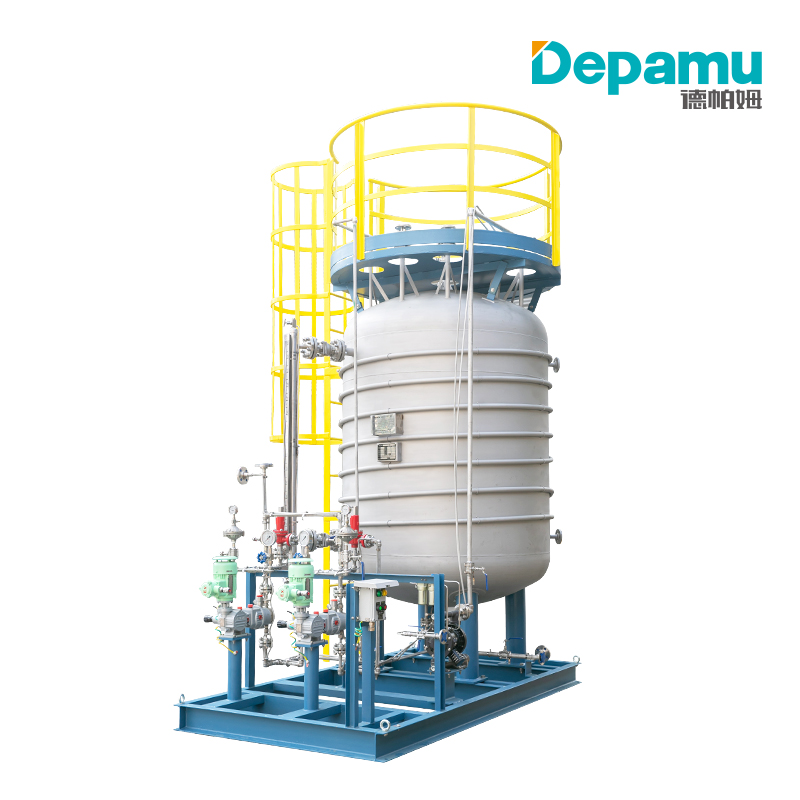
The Depamu skid is built around a modular, integrated design philosophy. All critical components—the solution tank, Metering Pumps, piping, instrumentation, and control panel—are mounted on a single structural steel base. The base frame is typically fabricated from heavy-gauge steel beams (such as I-beams or channel sections) designed to withstand vibration, seismic activity, and the stresses of lifting and transport. The frame incorporates integrated forklift pockets and lifting lugs in accordance with international lifting standards. A critical feature of the design is the full-perimeter drip tray or spill containment basin located beneath the pump and tank areas. This secondary containment is essential for environmental compliance, preventing chemical leaks from reaching the plant floor or the marine environment in offshore installations.
2.2 Solution Tank: The Chemical Reservoir
At the heart of the skid is the solution tank, which stores the corrosion inhibitor at the required working concentration. For corrosion inhibitor applications, Depamu offers tanks ranging from 0.5 m³ to 20 m³, depending on the application scale—smaller volumes for power plant boiler water treatment and larger volumes for oil gathering and transportation pipelines. Tanks are fabricated from corrosion-resistant materials such as SS316L stainless steel or high-density polyethylene (HDPE). For particularly aggressive inhibitor formulations, such as high-acidity scavengers, the tank may be constructed from duplex steel (2205) or lined with PTFE.
Standard tank features include magnetic level indicators for local visual monitoring, level transmitters (LSLL/LSL) connected to the control system for low-level alarms or automatic refill interlocks, and manways for inspection and cleaning. For powdered or viscous inhibitors, an electric agitator is provided to ensure solution homogeneity. Heating or cooling jackets are available as options for viscous inhibitors that require temperature control to maintain proper fluid viscosity.
2.3 Metering Pumps: The Precision Engine
The accuracy of the Depamu skid is defined by its metering pumps. Unlike standard centrifugal pumps, metering pumps—typically reciprocating Diaphragm Pumps—deliver precise displacement independent of discharge pressure fluctuations. Depamu configures these skids with high-performance metering pumps having capacities ranging from 10 liters per hour to 1,000 liters per hour, with discharge pressures from 0.3 MPa to 4.0 MPa for standard configurations, and custom high-pressure variants reaching up to 32 MPa (approximately 4,600 psi) for deep-well injection. The pumps are engineered for volumetric accuracy of ≤±0.5%, with 0–100% stepless stroke adjustment and leak-free PTFE double-diaphragm construction suitable for corrosive and volatile chemicals.
3. The Engineering Rationale for Duty/Standby Pump Redundancy
3.1 The “One Tank + Two Pumps” Configuration
A defining feature of the industrial skid design is the “1 Tank + 2 Pumps” configuration, which is the standard redundancy architecture for critical corrosion inhibitor service. One pump serves as the primary “Duty” unit, while the second functions as the “Standby” unit. This arrangement recognizes a fundamental reliability truth: even the most robust metering pump requires periodic maintenance, and unexpected failures—diaphragm rupture, valve clogging, motor faults—can occur without warning. In a single-pump installation, any such event immediately halts inhibitor injection, leaving the protected asset exposed to corrosive attack for the duration of the repair.
3.2 Automatic Switchover and Control Logic
The standby pump is not merely a spare sitting idle; it is an active element of the control philosophy. Pressure switches or pressure transmitters monitor the discharge line of the duty pump. If the duty pump fails to maintain the required discharge pressure—or if the pump motor trips—the control system automatically starts the standby unit, ensuring uninterrupted chemical injection. This automatic switchover is typically implemented through the PLC or DCS, which also generates an alarm to notify maintenance personnel of the duty pump failure. In more advanced configurations, the control logic can detect specific fault conditions such as diaphragm rupture (loss of suction) or injection line blockage (rapid back-pressure rise) and execute a bumpless transfer to the standby pump while transmitting an alert via SMS or email.
The redundancy philosophy extends beyond the pump itself. The standby pump is kept in a ready-to-run condition, with its suction and discharge valves aligned so that it can be brought online either automatically or manually. Some operators implement a “lead-lag” rotation strategy, periodically swapping the duty and standby roles to ensure even wear distribution across both pumps. This practice, combined with routine preventive maintenance on the standby unit, maximizes the probability that the standby pump will perform reliably when called upon.
3.3 Redundancy in the Context of Flow Assurance
The importance of duty/standby redundancy becomes particularly clear when viewed through the lens of flow assurance and asset integrity management. Corrosion inhibitor films are not permanent; they require continuous replenishment to repair breaches and maintain protective coverage. A study of inhibitor persistence might specify that the chemical film remains effective for a certain duration—for example, 12 hours—meaning that any pump breakdown must be repairable within that window to avoid an uninhibited event. The standby pump effectively eliminates this vulnerability by providing immediate replacement capacity, converting a potential unplanned shutdown into a controlled maintenance activity.
4. Operational Mechanism: From Tank to Process Line
The Depamu skid operates on a closed-loop feedback principle, with the objective of maintaining the inhibitor concentration in the main process stream at a specified target level (typically measured in parts per million, ppm). The operational sequence proceeds through four distinct stages.
Step 1: Chemical Preparation. The operator introduces the concentrated inhibitor into the solution tank, where it is automatically diluted with water or solvent to the required working concentration. The agitator ensures homogeneous mixing.
Step 2: Dose Control. The control system (PLC) receives a 4–20 mA signal from a flow meter installed on the main process line—the parent fluid (oil, gas, or water) whose flow rate determines the required inhibitor dose. The PLC calculates the necessary pump speed (stroke length and frequency) and adjusts the metering pump accordingly. If the main process flow increases, the PLC commands the pump to increase its stroke rate; if the flow decreases, the pump slows down.
Step 3: Injection. The chemical is drawn from the tank through a Y-strainer (to protect the pump from debris) and enters the pump head, where it is pressurized to a level slightly above the process line pressure. The fluid then passes through a calibration column—a transparent cylinder that allows operators to verify actual flow via a “drip test” method—and a safety relief valve (set to protect the pump in the event of a nozzle blockage). Finally, the chemical passes through an injection quill, a special nozzle that extends into the center of the pipe to ensure the inhibitor is introduced into the turbulent core of the flow rather than merely running along the pipe wall.
Step 4: Safety Interlocks. If the main process line pressure exceeds the pump’s rated pressure, or if the solution tank runs empty, the system automatically shuts down the pump and transmits an alarm to the Distributed Control System (DCS). Low-level pump stop, overpressure shutdown, and pump failure alarms are standard integrated interlock functions.
5. Materials Selection and International Standards Compliance
Material selection for the Depamu skid is governed by strict metallurgical and polymer compatibility criteria. All wetted components—pump heads, valves, seals, and piping—must resist the specific chemical properties of the inhibitor formulation. Because corrosion inhibitors may be alkaline (amine-based) or acidic, Depamu specifies pump heads in Hastelloy C276, titanium, or PVDF (Kynar) for aggressive acidic inhibitors, with SS316L as the default material for standard applications.
The skid is manufactured to comply with or exceed several international standards. ASME B31.3 governs process piping, ensuring that the skid’s piping is safe at rated pressures. NACE MR0175/ISO 15156 addresses materials for sour service (H₂S-containing environments), ensuring resistance to sulfide stress cracking (SSC). ATEX/IECEx certification applies to electrical enclosures (motors, junction boxes) when the skid is located in Zone 1 or Zone 2 hazardous areas. The metering pumps themselves are typically designed to API 675 standards, the recognized specification for controlled-volume positive-displacement pumps in petroleum, petrochemical, and natural gas industries.
6. Control and Automation Philosophy
Modern Depamu skids are transitioning from manual stroke-length adjustment to intelligent instrumentation. The skid includes a NEMA 4X (IP66) local control panel, typically equipped with an HMI touchscreen and housing the PLC. In local mode, the operator uses the HMI to start or run manual batch injection. In remote mode, the PLC receives commands (start/stop, setpoint) from the central plant DCS via Modbus TCP/IP or Profibus.
Advanced diagnostic capabilities are a hallmark of the modern skid. Vibration sensors mounted on the pump motor and pressure sensors positioned before and after the pump enable the control logic to detect conditions such as diaphragm rupture (loss of suction) or injection line blockage (rapid back-pressure rise). Upon detection of a fault, the system executes an automatic switchover to the standby pump and notifies maintenance personnel through SMS or email alerts, achieving a level of self-diagnosis and alarm output that supports unattended continuous operation.
7. Applications Across Industrial Verticals
The versatility of the Depamu corrosion inhibitor skid is demonstrated by its deployment across diverse industrial sectors.
Upstream Oil and Gas. Produced crude oil contains formation water (brine) and H₂S/CO₂ gases, and corrosion rates peak as pipeline pressure declines. Depamu high-pressure skids (up to 30,000 psi) inject film-forming inhibitors directly into the well annulus or gathering manifold, with small-volume, high-pressure diaphragm pumps often integrated with solar power control systems for remote wells.
Downstream Refining. In crude distillation units, overhead systems condense HCl and H₂S to form a highly corrosive “sour water” zone. Depamu employs low-flow, high-turn-down-ratio pumps to inject neutralizer amines and film-forming inhibitors, maintaining a precise pH range of 5.5 to 6.5 in the overhead receiver to prevent tray and condenser tube damage.
Thermal Power Generation. Dissolved oxygen in boiler feedwater causes oxygen corrosion in boiler tubes, leading to catastrophic ruptures. Depamu integrates oxygen scavenger injection skids with deaerator level control systems, injecting chemicals downstream of the deaerator and closing the control loop with a redox potential (ORP) analyzer.
Circulating Cooling Water. Cooling towers expose metal surfaces to oxygen, biological growth, and scaling ions. Skids typically employ a “2 Tanks + 3 Pumps” configuration, with one tank containing corrosion inhibitor and the other containing biocide, alternating injection cycles to maintain both corrosion protection and biological control.
8. Operational Advantages and Economic Justification
The economic case for a factory-built Depamu skid, rather than a field-assembled system, rests on several quantifiable advantages. Installation costs are significantly reduced: while the initial material cost of a skid may be higher than that of bulk pumps and tanks, the installation cost is dramatically lower. A field-assembled system requires weeks of scaffolding, welding, and electrical wiring, whereas a skid requires a single crane lift and connection of four interface points: power input, chemical suction (if the bulk storage tank is remote), injection line output, and the signal cable to the DCS. Factory Acceptance Testing (FAT) provides risk transfer: before the skid leaves the Depamu factory, it undergoes hydrostatic and functional testing, with all leak points repaired and all logic circuits verified, ensuring that manufacturing defects are not discovered during a plant shutdown. Footprint optimization is particularly critical in offshore oil and gas (FPSO) applications, where deck space carries a premium and the compact, modular skid design minimizes the required real estate.
9. Maintenance and Reliability Considerations
The presence of a standby pump fundamentally alters the maintenance strategy for the injection skid. With a duty/standby configuration, preventive maintenance on the standby pump can be performed while the duty pump continues to protect the asset, and vice versa. A typical maintenance schedule includes daily manual checks that the duty pump is operating and that inhibitor tank levels are adequate; quarterly manual verification of the pump injection rate; and annual planned pump maintenance. The ability to isolate, flush, and service one pump while the other remains in service ensures that maintenance activities never compromise inhibitor delivery.
It is important to note that positive displacement metering pumps must never be operated against a closed valve. The skid’s piping design incorporates a full-flow bypass relief valve, factory-set to protect the pump and associated piping from overpressure. Proper commissioning and operating procedures emphasize this requirement, along with the importance of venting the pump head and discharge line before startup.
10. Conclusion
The Depamu Corrosion Inhibitor Injection Skid, configured with a dedicated duty pump and an additional standby pump, represents a mature engineering response to the dual challenges of corrosion control and operational reliability. By integrating chemical storage, precision metering, closed-loop control, and full duty/standby redundancy into a single factory-tested package, the skid ensures that the protective inhibitor film is maintained without interruption, even in the event of a pump failure. The design’s compliance with ASME, NACE, ATEX, and API 675 standards, its robust material selection for aggressive chemical service, and its advanced diagnostic and switchover capabilities make it suitable for the most demanding applications—from remote wellheads and sour gas gathering systems to refinery overhead condensers and critical boiler feedwater circuits. In an era where asset integrity and unplanned downtime carry ever-higher economic and environmental consequences, the duty/standby injection skid is not merely a convenience but a cornerstone of responsible chemical treatment program design.