

In the global quest for energy, the journey of crude oil from deep geological formations to a refinery is rarely a simple matter of drilling a hole and waiting for nature to provide. In fact, the most prolific phase of an oil field’s life—the period of "natural flow"—is often relatively short. As reservoir pressure depletes over time, the relentless natural drive that pushes hydrocarbons to the surface weakens, leaving vast quantities of oil trapped underground, sometimes as much as 60-70% of the original oil in place (OOIP). To recover this dormant resource, the industry turns to Enhanced Oil Recovery (EOR) techniques, the most common and fundamental of which is waterflooding.
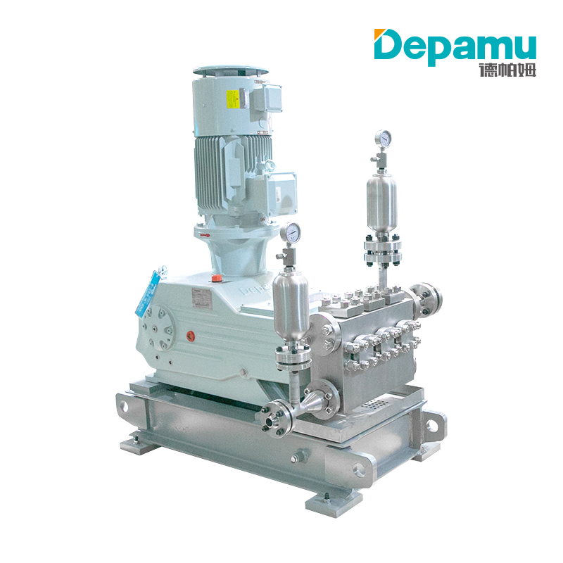
At the heart of any waterflooding operation lies the water injection pump. Far from being a simple water mover, this pump is a high-pressure, high-reliability piece of industrial machinery responsible for transforming low-pressure source water into a high-velocity, high-pressure fluid capable of pushing oil through porous rock towards production wells. This article provides a comprehensive, technical explanation of how Water Injection Pumps work, detailing their system context, principal types, mechanical operation, and the critical auxiliary systems that ensure their survival in the harsh environment of an oil field.
Section 1: The Big Picture – Why Water Injection?
Before dissecting the pump itself, one must understand the reservoir dynamics that necessitate it. An oil reservoir is not an underground lake of oil; it is a complex matrix of porous sandstone or limestone, with pores saturated by oil, water, and gas. Primary recovery relies on natural energy sources: gas cap expansion, rock compaction, or water encroachment (aquifer drive). As oil is produced, pressure drops. At a certain point, called the bubble point, gas comes out of solution, and the oil becomes viscous and immobile.
Water injection, or waterflooding, serves two primary functions:
-
Pressure Maintenance: By injecting water into the reservoir (typically through dedicated injection wells on the periphery or within the field), the declining reservoir pressure is arrested and stabilized. This maintains the drive energy that pushes oil towards the production wells.
-
Sweep Efficiency: Water physically sweeps oil from the pores of the rock. As water is immiscible with oil (they don't mix), the injected water pushes the oil ahead of it, like a piston, towards the production wells.
The water injection pump is the hydraulic heart of this system. It must take in water from a source (e.g., seawater, produced water, or an aquifer), overcome the resistance of the wellbore, the formation's permeability, and the back-pressure of the reservoir, and deliver it at a precise, high pressure—often ranging from 1,000 to 10,000 pounds per square inch (psi) or higher for deep or tight formations.
Section 2: System Architecture – The Path of the Injected Water
A water injection pump does not work in isolation. It is one component of a sophisticated surface facility. The typical water injection flow path includes:
-
Water Source: This can be a freshwater lake, a shallow aquifer, or, most commonly offshore, seawater. Increasingly, operators reuse "produced water" (water that comes up with the oil) to reduce environmental impact.
-
Water Treatment System: This is the most critical precursor to the pump. Raw water contains solids, oil droplets, bacteria, and dissolved oxygen. These are disastrous for the pump and the reservoir. Treatment includes:
-
Filtration: Removing suspended solids (down to 1-5 microns) to prevent plugging of the pump seals and the reservoir pores.
-
Deaeration (Deoxygenation): Dissolved oxygen is highly corrosive to steel pipes and pumps. Vacuum towers or chemical scavengers (e.g., sodium sulfite) remove oxygen to parts-per-billion levels.
-
Biocide Treatment: To kill sulfate-reducing bacteria (SRB) that produce toxic hydrogen sulfide and clog formations.
-
-
Booster Pumps: Low-pressure centrifugal pumps that draw treated water from the holding tanks and provide Net Positive Suction Head (NPSH) to the main high-pressure injection pump.
-
Main Water Injection Pump: The focus of this article. This machine boosts the water pressure from 50-100 psi to the required injection pressure (up to 10,000+ psi).
-
High-Pressure Distribution Manifold: A network of thick-walled steel piping that distributes water to individual injection wells.
-
Wellhead and Downhole Tubing: The water travels down the well, often through a packer that isolates the injection zone, and enters the formation.
Section 3: The Heart of the Matter – How the Pump Works (Basic Principles)
All pumps function by converting mechanical energy (from an electric motor or engine) into hydraulic energy. This is achieved by either imparting velocity (kinetic energy) and converting it to pressure, or by directly displacing a fixed volume of fluid.
In the context of high-pressure water injection, two families of pumps dominate:
-
Centrifugal Pumps (specifically Multi-Stage Barrel Pumps): Used for moderate to high flow rates and moderate pressures (up to ~3,000 psi).
-
Positive Displacement Pumps (specifically Reciprocating Plunger Pumps): Used for low to moderate flow rates and very high pressures (up to 10,000+ psi).
We will examine both, but focus on the reciprocating plunger pump due to its prevalence in high-pressure onshore injection, while explaining the centrifugal variant for offshore or high-volume applications.
Section 4: The Reciprocating Plunger Pump – The High-Pressure Champion
This is the workhorse for most onshore waterflood projects. Its principle is simple: a plunger reciprocates in a cylinder, displacing a fixed volume of water with each stroke.
Step-by-Step Operation (Single Cylinder):
-
Suction Stroke: The plunger retracts (moves backward). The increasing volume in the cylinder creates a pressure drop. The suction valve (a spring-loaded check valve) opens, and water at low pressure (from the booster pump) flows into the cylinder. The discharge valve remains closed.
-
Discharge Stroke: The plunger advances (moves forward). The pressure inside the cylinder rises dramatically. The suction valve is forced shut, and the discharge valve opens. The trapped water is pushed out into the high-pressure manifold. The pressure rises to the level required to inject into the reservoir.
The Multi-Plunger (Triplex or Quintuplex) Configuration:
A single cylinder would produce a pulsating flow—high pressure followed by zero flow. To create a smooth, near-continuous flow, multiple plungers are arranged 120° apart (triplex – three plungers) or 72° apart (quintuplex – five plungers). Their strokes overlap. As one plunger finishes its discharge stroke, another is at its peak, ensuring that pressure pulsations are minimized to within 5-10% of the average pressure.
Key Components and Their Functions:
-
Plunger: A highly polished, hard-coated (often ceramic or chromium oxide) rod that reciprocates. It is the direct contact surface to the water. Its diameter and stroke length determine the displacement volume.
-
Packing (Seals): A set of V-shaped, resilient rings (usually PTFE, PEEK, or polyurethane) that seal the annular gap between the reciprocating plunger and the stationary cylinder. They allow linear motion while preventing high-pressure water from leaking out.
-
Fluid Cylinder (Liquid End): The forged steel block containing the cylinders, suction, and discharge valves. It is designed to withstand extreme fatigue from cyclic pressure.
-
Suction & Discharge Valves: Spring-loaded, poppet-style or plate-type check valves. They open and close thousands of times per hour. Their material is hardened stainless steel or tungsten carbide to resist erosion from residual sand or debris.
-
Power Frame (Power End): The robust cast iron or steel housing containing the crankshaft, connecting rods, and crosshead. It converts the rotary motion of the electric motor into the linear reciprocating motion of the plunger.
-
Crosshead: The critical sliding component that connects the connecting rod to the plunger rod. It moves linearly within guides, preventing side-loads from damaging the plunger packing.
Operational Cycle in Numbers:
Assume a triplex pump with a 4-inch plunger, 6-inch stroke, operating at 300 strokes per minute.
-
Displacement per stroke (per cylinder) = Plunger Area × Stroke Length = (π × 2²) × 6 = 75.4 cubic inches.
-
Flow rate ≈ 3 cylinders × 75.4 cu in × 300 rpm ≈ 67,860 cu in/min ≈ 293 gallons per minute (GPM).
-
At 5,000 psi discharge pressure, the power required is approximately: (GPM × psi) / (1,714 × Efficiency). At 90% efficiency, this is roughly 950 horsepower.
Section 5: The Multi-Stage Centrifugal Pump – High Volume, Moderate Pressure
For offshore platforms or large onshore fields requiring 200,000 barrels of water per day or more at 2,000 psi, centrifugal pumps are preferred. A single-stage centrifugal pump uses a rotating impeller to fling water outward, converting velocity to pressure. For high pressure, multiple stages are stacked in series within a single "barrel" casing.
How it Works:
-
Water Entry: Water enters the pump eye (center of the first impeller).
-
Impeller 1: The impeller rotates at 3,600 RPM (for a 2-pole motor). Centrifugal force accelerates water to the outer rim, where it leaves at high velocity and moderate pressure (e.g., 150 psi).
-
Diffuser (or Return Channel): Stationary vanes surrounding the impeller capture the high-velocity water, gradually slowing it down to convert kinetic energy into pressure (Bernoulli’s principle). The diffuser then redirects water to the eye of the next impeller.
-
Subsequent Stages: The process repeats 5 to 20+ times. Each stage adds incremental pressure (typically 100-300 psi per stage). By the time water exits the final stage, the cumulative pressure reaches the target (e.g., 2,500 psi).
Key Characteristics:
-
Smooth, Pulsation-Free Flow: Ideal for systems sensitive to vibration.
-
Rotary Motion: No reciprocating parts, leading to less wear on seals over time.
-
Sensitivity to Gas: Centrifugal pumps "cavitate" badly if any entrained gas (including small bubbles) enters the suction. Deaeration must be absolute.
-
Performance Curve: Flow varies with pressure. If backpressure increases, flow decreases. At zero flow (deadhead), pressure rises to a maximum (shut-off head), which can be dangerous.
Section 6: The Critical Role of Auxiliary Systems
A water injection pump is only as reliable as its support systems. The two most vital are the seal system and the lubrication system.
1. High-Pressure Sealing (The Packing & Flush System):
In a plunger pump, the dynamic seal (packing) is the weakest link. Water is a poor lubricant. At 5,000 psi, the packing generates immense friction and heat. Without intervention, it would fail in minutes. The solution is a packed plunger flush system:
-
Water is bled from the pump discharge, passed through a pressure-reducing regulator and a 1-micron filter, and injected into a lantern ring (a grooved spacer between packing rings).
-
This injected water lubricates the plunger, removes frictional heat, and flushes away any abrasive particles.
-
The flush water leaks past the packing at a controlled rate (visible as a drip or fine spray) – this is called "allowable leakage." If it stops leaking, the packing is too tight and will burn up. If it leaks too much, the packing is worn.
2. Power End Lubrication:
The crankshaft, connecting rod bearings, and crossheads operate under high loads. A forced-feed lubrication system circulates ISO VG 150 to 460 grade oil. This oil is cooled by a heat exchanger (water or air) and filtered. Low oil pressure or contamination will trigger an emergency shutdown.
3. Pulsation Dampeners:
Even a triplex pump has residual pulsations. On the discharge side, a pulsation dampener (a pressure vessel with a bladder pre-charged with nitrogen) acts as a shock absorber. It smooths flow to protect downstream piping, flow meters, and wellheads from fatigue failure. A suction dampener ensures smooth flow into the pump to prevent cavitation.
Section 7: Operational Challenges and Mitigation
Despite robust design, water injection pumps face daily challenges:
-
Corrosion-Erosion: Sand or other solids in the water act like a sandblaster on valves and plungers. Mitigation: superior filtration (down to 1 micron) and using tungsten carbide or ceramic materials.
-
Cavitation: If the suction pressure is too low, water vaporizes into bubbles that collapse violently on the plunger or impeller, pitting metal. Mitigation: maintaining adequate NPSH (ensuring the booster pump is working correctly) and avoiding hot water (which vaporizes more easily).
-
Packing Failure: The most common failure mode. As packing wears, leakage increases. Operators monitor a "leak-off line" flow meter. When leakage exceeds a threshold (e.g., 2 gallons per minute), the packing must be replaced.
-
Vibration: Depamu-pumps.com/Reciprocating-Pumps.html target='_blank'>Reciprocating Pumps generate torsional vibrations that can crack crankshafts. Properly tuned pulsation dampeners and regular vibration monitoring are essential.
Section 8: Control and Automation – The Smart Pump
Modern water injection pumps are not run manually. A Variable Frequency Drive (VFD) controls the speed of the electric motor. The VFD receives a setpoint from the central control room, which is determined by the reservoir engineer's injection plan. The control logic works as follows:
-
Pressure Control: The VFD adjusts motor speed (RPM) to maintain a constant discharge pressure. As reservoir pressure builds, the pump slows down.
-
Flow Control: Alternatively, the VFD can maintain a constant flow rate (e.g., 150,000 barrels per day), allowing pressure to vary.
-
Safety Shutdowns: Programmable Logic Controllers (PLCs) monitor:
-
High discharge pressure (causes rupture)
-
Low suction pressure (causes cavitation)
-
High power end temperature (oil failure)
-
High packing leak-off (seal failure)
-
Vibration spikes
Any violation triggers an automated shutdown, often within milliseconds to prevent catastrophic damage.
-
Conclusion
The water injection pump is a masterpiece of mechanical engineering, perfectly adapted to a brutal operational environment. Whether it is the massive, smooth-turning multi-stage centrifugal pump on an offshore platform pushing 300,000 barrels of deoxygenated seawater a day, or the robust, rhythmic thumping of a quintuplex plunger pump forcing water into a tight shale formation at 8,000 psi onshore, the mission is the same: to breathe life back into a dying reservoir.
Understanding how these pumps work—from the basic principle of volume displacement or velocity-to-pressure conversion, to the intricate dance of the plunger, packing, and flush system—reveals the sophisticated technology behind the seemingly simple concept of "pushing water into the ground." As oil fields mature globally and the demand for EOR grows, the water injection pump will remain an indispensable tool, quietly and relentlessly driving the secondary recovery that provides a significant fraction of the world’s oil. Its efficient, reliable operation is not just a matter of mechanical maintenance; it is a core pillar of global energy production.